By Gregory A. Henry
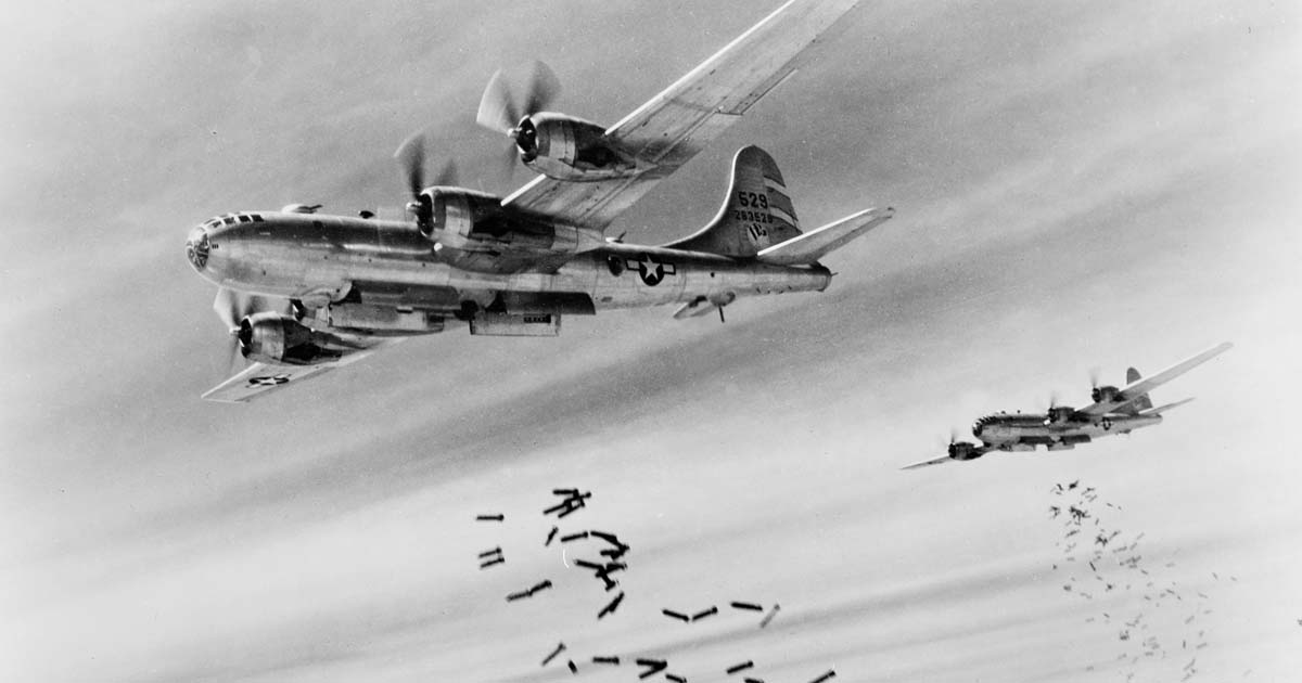
The Boeing B-29 Superfortress was a game changer. First rolling off the assembly line as a production aircraft in July 1943, the Superfortress was the answer to America’s need for a high-level long-range strategic bomber. Conceived in 1938, the Superfortress was designed to increase the range, payload, and speed of its predecessors and was ultimately slated for service in the Pacific Theater of Operations only. The B-29 had a loaded range of around 4,000 miles, could carry a bomb load of up to 20,000 pounds, had a combat ceiling in excess of 36,000 feet, and travelled at a maximum speed of over 350 miles per hour with a cruising speed of 230 miles per hour. No other bomber in the world approached its capabilities.
The Superfortress also influenced American strategy in the Pacific. Already masters of the Solomon, Gilbert, and Marshall Islands, American strategists elected to bypass the Japanese stronghold in the Caroline Islands and instead turn their attention to the Marianas Islands. Their decision was influenced in part by the availability of the new B-29 bomber, which could easily reach the mainland of Japan some 1,500 miles away from the Marianas islands of Saipan, Tinian, and Guam.
The B-29 also brought a number of technological innovations to America’s existing air arsenal. It was the first plane to feature a heated, pressurized crew cabin, which greatly improved crew comfort and combat effectiveness while decreasing their fatigue. With pressurization, the B-29 could operate at significantly higher altitudes than previous bombers and often above the ceiling of enemy fighters. It was also the first bomber to pioneer dual-wheeled tricycle landing gear. Previously, the B-17 Flying Fortress featured a tail wheel and the B-24 Liberator a single nose wheel, which made the latter notoriously unstable on landing. Without discounting these aeronautical innovations, what really distinguished the B-29 from every other bomber in the world was its state-of-the-art gunnery system, which made it quite literally a flying superfortress.
The aircraft featured a General Electric Company model 2CFR55B1 centralized fire-control system, or CFC, which transformed bomber defensive gunnery from a loose collection of independent guns into an integrated gunnery system. The major components of the CFC system were five gunsights, five remotely controlled turrets, five targeting computers, and an electric gun-switching system. Each of the five turrets was operated remotely by a gunner stationed in one of five sighting stations located throughout the aircraft. The firing trajectory was calculated by five targeting computers, each associated with a sighting station and each connected to one or more turrets that could be operated from that single sighting station.
Two turrets were located in the forward section of the aircraft, with the upper forward turret on top of the fuselage and the lower forward turret on the bottom, both positioned slightly aft of the forward pressurized crew compartment where the pilot, co-pilot, flight engineer, and navigator sat. Similarly, the upper aft and lower aft turrets were located on the top and bottom of the fuselage toward the rear of the aircraft forward of its tail fin. The fifth was mounted in the tail facing the rear.
The B-29 carried a crew of 11 airmen, five of whom were gunners. The fire control officer, also called the ring gunner or top gunner, sighted through a plexiglass blister on top of the fuselage and were seated in the middle pressurized crew compartment in a tall chair known as the “barber chair.” The right- and left-side gunners, or blister gunners, were stationed below the top gunner, sighting through blisters on opposite sides of the fuselage. The bombardier sat in the nose of the aircraft, forward of the pilot and co-pilot, and functioned as the nose gunner when not engaged in the actual bombing run. The nose gunner’s gunsight retracted to be stowed out of the way when he turned his attention to the bombsight, which was affixed to the floor between his feet. Finally, the tail gunner sat in the rear of the airplane alone in the aft pressurized compartment.
One gunner was assigned primary control or “first call” on the use of each of the five turrets. Through a series of electrical switches, control of the turret could be passed to a secondary gunner who could operate it alone or in conjunction with his primary turret. The nose gunner had primary control of both forward turrets. Secondary control of the upper forward turret fell to the top gunner; the lower forward turret was controlled by either of the side gunners. The top gunner had primary control of the upper aft turret and secondary control of the upper forward turret. The side gunners had primary control of the lower aft turret with secondary control of the lower forward turret and the tail turret. The tail gunner could only control the tail turret.
With all the overlapping fire control possibilities, proper communication among the gunners via the aircraft’s interphone system was paramount, with the fire control officer quarterbacking the whole process. The gun positioning system, with the exception of the tail mount, contained fire interrupter cams, which prohibited the guns from firing on their own aircraft’s wings or tail. However, the guns could fire on their own formation if the weapons were active at the time when control switched between gunners and the guns swung around to the second gunner’s targeting position.
Each of the five turrets featured two air-cooled Browning M2 .50-caliber machine guns. In response to the relative effectiveness of frontal attacks, later versions of the aircraft included two additional .50s in the upper forward turret. To avoid overheating the guns, gunners were instructed to fire in short bursts and then count to three before firing again. Hot gun barrels would expand, decreasing accuracy, or could rupture completely or “cook off” the next round by thermally induced firing. A maximum of 25 rounds could be fired at once but then required at least 15 seconds of cooling off, which must have seemed like eternity when engaged with the enemy. Early B-29 models also included a 20mm cannon in the tail mount. The cannon was controlled by the same sighting and firing mechanism as the rear machine gun turret and could be fired in conjunction with the machine guns but not alone. The 20mm round weighed about twice as much as the .50-caliber round but packed nearly three times its force.
Each gunner manually operated a gunsight, which was connected electrically to the CFC system and contained a 2-inch by 3-inch glass eyepiece. The glass optics had two interchangeable sky filters, enabling the gunner to maintain a clear view of his target through the optics in nearly dark conditions or even sighting an enemy attacking from out of the sun. A reticle consisting of a circle of dots aligned around a center dot, similar to the crosshairs on a rifle scope or the focusing marks on a camera viewfinder, was reflected on the optical glass by a reticle lamp of adjustable illumination.
When a target was encountered, the gunner was required to first visually identify the type of enemy aircraft and then adjust the target size knob on the gunsight from 35 feet to 150 feet to correspond with the wingspan of the target aircraft. The projected reticle size changed as the target size knob was adjusted, showing the current target size setting in feet at the 12 o’clock position on the reticle circle. Placing the center dot of the reticle on the center of the target, the gunner would then adjust the gunsight’s range wheel until the target aircraft’s wings completely filled the reticle circle.
Tracking the target then required the smooth movement of the gunsight on both the vertical axis, or elevation, and on the horizontal axis, or azimuth, to keep the target aircraft centered in the reticle and properly ranged within the bounds of the reticle circle. Changes in azimuth were affected by the gunner rotating the gunsight horizontally along with his body, while changes in elevation required moving the gunsight vertically by rotating the two hand wheel grips that were located on the outsides of the gunsight frame. Friction adjustments allowed the gunner to customize the touch of the gunsight’s movements to his preference.
Each movement in the gunsight, whether in elevation or in azimuth, resulted in an electrically activated corresponding movement to the guns (elevation), the turret (azimuth), or both. The mechanism for transmitting these movements involved differential selsyn generators in the gunsight and at the gun emplacement as well as a servo amplifier and two amplidyne generators, which drove the two motors that moved the guns.
With the exception of the tail mount, the turrets could rotate 360 degrees in azimuth and the guns could incline to 90 degrees in elevation relative to the body of the aircraft. The firing triggers were not “pulled” per se, but rather were buttons located adjacent to the hand wheels and depressed by either of the gunner’s thumbs. An action switch depressed by the gunner’s left palm while in contact with the hand wheel served as a control override for the sighting station. If the action switch was not depressed, such as in the event the gunner was incapacitated, the guns could not be fired from that sighting station. Control of the turret(s) then passed to another gunner’s sighting station regardless of the current settings of the electrical control switches, ensuring that all turrets remained operational.
While in contact with the enemy, the gunner simply needed to properly size, range, and track the target with his gunsight and then fire at the appropriate effective range. The CFC system moved the guns while the computer continuously calculated all the corrections needed for the fired projectile to hit the target. With computer-calculated targeting, the effective range of the guns was 900 yards, 50 percent farther than manually sighted guns and over twice the effective range of most enemy fighters’ guns.
The computer introduced the correction as a deviation from the parallel mirroring movements between the gunsight and the guns as transmitted by the system of selsyns. The total calculated correction was the sum of individual corrections for ballistics, parallax, and lead. Ballistics corrections compensated for the deflection of the projectile caused by gravity and by wind as the projectile exited an aircraft traveling around 250 miles per hour. Since the guns themselves were remote from the gunsights, parallax correction allowed for the distance along the length of the aircraft between the gunsight and the gun barrels. Lead correction allowed for the travel distance of the target aircraft during the time the projectile was in the air.
To perform its correction calculations, the computer required a number of pieces of input information obtained from several different sources. These inputs included the current position of the guns in both elevation and azimuth; the aircraft’s true air speed, altitude, and outside temperature, which were input by the aircraft’s navigator; the range to the target obtained from the gunsight as the gunner tracked the target and adjusted the range wheel; and the relative velocity of the target received from two gyroscopes located on the gunsight as the gunner tracked the target.
Depending on the type of parallax, two different models of computers were used. A single-parallax computer, the General Electric model 2CH1C1, was used at sighting stations that had parallax between the gunsight and only one gun location, such as the tail gunner station, which controlled only one turret, or the nose gunner station, whose two turrets were located above and below each other almost equidistant longitudinally from the gunsight. A double-parallax computer, the model 2CH1D1, was used for the three top and side gunners’ sighting stations since all three gunners could simultaneously control two turrets of differing parallax from their gunsight. Although the side gunners were capable of controlling three different turrets via the control switching system, they could only operate two at any one time.
All inputs to the computer were electrical, but the computer itself performed its calculations mechanically since a purely electrical calculator lay outside the reach of existing technology in the era of vacuum tubes with their appetite for electrical current and enormous heat output. Aboard an aircraft, size and weight were further concerns. Conversion of the electrical inputs into the mechanical calculation system was achieved through an array of selsyns and potentiometers.
The computer itself was really several separate but interconnected calculating units contained within the same chassis, which was the size of a suitcase and weighed more than 50 pounds. The ballistic calculating unit was programmed with the known effects of gravity and the ballistic characteristics of a .50-caliber shell fired from the Browning M2, such as its muzzle velocity. To make the ballistics correction calculation, the ballistic unit needed to know the current gun position for the angle of initial velocity, the range to the target, the current true air speed, which affected windage, and the aircraft’s current altitude and outside temperature, which affected the air density and thus the drag on the bullet. Similarly, the parallax computing unit was programmed with the longitudinal distance(s) between its gunsight and the turret(s) that sight could control, but it needed to know the current gun position and the range to the target to compute the parallax correction trigonometrically. Finally, the lead calculating unit computed the lead correction from the range and the relative velocity of the target along with the ballistic characteristics, which affected the time of the projectile to the target.
The computer’s output, which consisted of the parallel signal received from the gunsight selsyn adjusted for the sum of the three calculated corrections, was then converted back into electrical impulses, which fed a servo amplifier, or feedback controller, that drove the two gunpositioning motors, one for elevation and one for azimuth. Thus the computer’s correction was introduced as an alteration to the position of the guns and of the turret from that which would have been exactly parallel to the gunsight’s position.
Because they were connected electrically, the computers did not have to be physically located with either the gunsights or the turrets. The nose gunner’s computer was located in the forward pressurized cabin aft of the pilot’s armor, while the other four computers were placed under the floor in the radar operator’s compartment near the back of the middle pressurized cabin surrounded by armor. In case of a computer failure or combat damage, an override switch allowed the gunner to bypass the computer completely and operate the guns without its correction using a retractable flip-down peep sight on the gunsight.
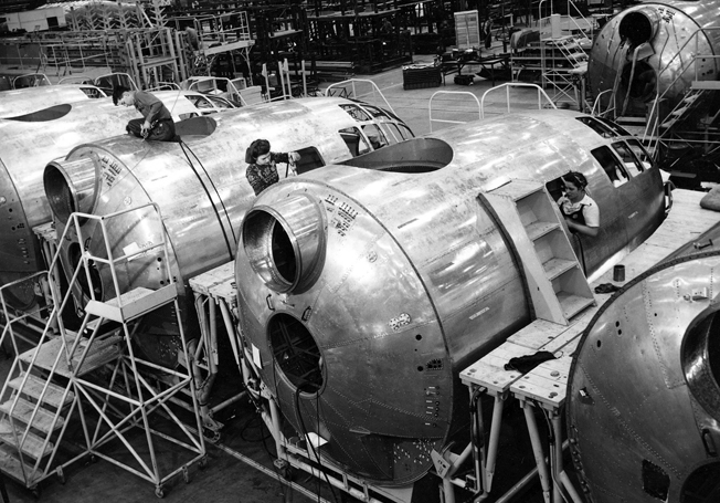
According to U.S. Army Air Forces records, a total of 3,760 production Superfortresses were delivered, around 70 percent of which were built by Boeing at its plants in Wichita, Kansas, and Renton, Washington. The rest were produced in Marietta, Georgia, by the Bell Aircraft Company and in Omaha, Nebraska, by the Glenn L. Martin Company, later part of Martin-Marietta.
After assembly was complete but before the aircraft was combat ready, the guns were harmonized and the targeting computers tested. First, both guns in a single turret were aligned to parallel target marks by use of a bore sighting tool with alignment made by changes to adjustment screws. Then each turret was aligned with each of the sighting stations that could control it by using a predefined harmonization target placed at least 100 feet away from the aircraft. Adjustments were made to either the selsyn at the sighting station or to the one at the turret, depending on which gunsight and turret combination was being adjusted. After the guns and sighting stations were harmonized, the targeting computers along with all the input systems and calculating components were tested using a comprehensive testing device containing on its face over 50 dials, meters, and switches.
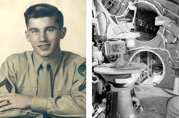
Aircraft production quickly outpaced the manufacturers’ capacity to set up the revolutionary CFC systems, so the USAAF began training its own crews to ensure that the otherwise combat-ready bombers were not delayed in deployment. USAAF Corporal Robert W. “Bob” Truxell of Lansing, Michigan, was part of the first class to graduate from the B-29 CFC and computer training schools at Lowry Field in Denver, Colorado. Truxell had previously washed out of air cadet pilot training due to a three-month bout with rheumatic fever, which permanently disqualified him from serving in a flight crew. The illness proved to be fortuitous since most of his air cadet squadron was later lost in the ill-conceived raid on the Ploesti, Romania, oil refineries on August 1, 1943. After recovering from his illness, Truxell was reassigned from air cadets to aircraft armament, where he completed the remote control turret mechanic course.
After the turret course, Truxell was tapped for the 16-week B-29 CFC specialist course because he had begun studying engineering, including taking trigonometry, at the General Motors Institute in Flint, Michigan, before enlisting in February 1943. Corporal Truxell finished first in his CFC class, earning entrance into targeting computer school and a third stripe upon its completion. Shortly thereafter he was given command of the first graduating class and a staff sergeant’s rocker. The new crew’s first assignment was in Georgia.
Truxell writes, “We were all sent to the [Bell Aircraft] B-29 factory in Marietta, Georgia, where completed B-29s were lined up for a mile awaiting proper alignment of the gun turrets and central computer.” He vividly recalls using a fire extinguisher to flush civilians sleeping on the clock at government expense out of the bombers’ pressurized crew tunnels so his crew could access the aft areas of the aircraft. Once the backlog in Georgia was cleared, the crew leapfrogged to various stateside air bases where B-29 squadrons were ready for overseas deployment—except for the final adjustment of their gunnery systems. After a particular squadron deployed, the gunnery crew moved on to the next base. Truxell calls his service a “pretty safe and interesting job.”
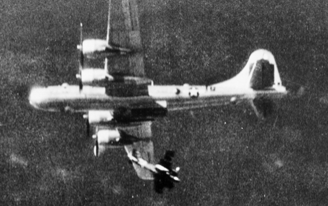
The B-29’s revolutionary gunnery system made a Japanese fighter pilot’s job neither pretty safe nor interesting. According to the Army Air Forces Statistical Digest published in December 1945, in the 13-month period from August 1944 to the war’s end in August 1945, B-29s were responsible for the destruction of 914 enemy aircraft in the air with a loss of just 72 of their own to enemy aircraft during more than 31,000 combat sorties flown.
Gregory A. Henry is a first-time contributor to WWII History and lives in Chattanooga, Tennessee. The author would like to acknowledge the Commemorative Air Force’s B-29/B-24 Squadron of Fort Worth, Texas, and Dave Santos of the New England Air Museum in Windsor Locks, Connecticut, for their assistance.
