By Mike McLaughlin
I was always fascinated by the mastery of water,” Sir Donald Coleman Bailey reflected, long after the end of World War II. “Water is a damnably difficult thing to tamper with.” Although initially employed by the Sheffield City Engineering Department to help build and maintain a reservoir, Bailey was always interested in bridges, and it was his later work with the British War Office that immortalized him. His major contribution to the Allied war effort was an invention—a lightweight, pre-fabricated bridge designed to help the Allied armies overcome practically any water obstacle anywhere in the world.
The inventor of the Bailey Bridge was a native of Rotherham, Yorkshire, and a graduate of Sheffield University’s engineering school, joined the Experimental Bridging Establishment (E.B.E.) in 1928. The organization had a small staff, mostly civilian, and a meager budget. Their mission was to propose modifications to the World War I-era bridging equipment used by the British army. This was an unenviable task made heavier as World War II approached.
Bridging equipment was a standard element of the Royal Engineers’ particular arsenal, since anywhere the British army went it was sure to encounter water obstacles. But by 1939, the engineers faced a dilemma. The standard model bridge, the Inglis, was a World War I throwback which could only carry a load of 19 tons. The standard British medium tank, the Matilda, weighed 23 tons, and future models would weigh nearly three more. And the proposed heavy tank, the Churchill, would weigh at least 40 tons. No amount of remodeling could give the Inglis the necessary strength to bear the weight of these vehicles.
Field Requirements Lead to Further Improvements
A better bridge was needed, but the approach of war and the logistical strains already placed on the British military and the economy behind it presented several non-negotiable conditions. The bridge needed to be designed and built in such a way so that it could be strengthened and, when necessary, repaired when it was already in place. Every one of the components had to be made with material already in use. There was neither the time nor the budget to develop new steel alloys. Since the pieces needed to be mass-produced, they had to be simple enough for any engineering firm to build. Each piece had to be light enough to be carried by either one man or a group of men. Each had to fit in the back of the 3-ton truck then in widespread use.
Lastly, the bridge needed to be relatively easy to build by hand. This last point was vital. Since cranes were required to lift the heavier pieces of other bridges into place, the speed with which any engineer unit could move would depend ultimately on the performance of its heavy-lift equipment. For instance, the U.S. Army’s H-10 and larger H-20 bridges had pieces weighing, respectively, over 1,100 and 1,700 pounds—far too heavy for men to move by hand.
With all this in mind, the War Office finally approved the concept Bailey had been pondering for years. Bailey turned to his colleagues, Major Ralph Freeman, R.E. (Royal Engineers), who had designed the Sydney Harbor Bridge in Australia, and Major H.A.T. Jarrett-Kerr, R.E., to help work out the specifics for each component. The scheme used the same principles as the popular Erector and Meccano building sets,—there was a uniformity to the pieces; compared to the parts for earlier bridge types, they were fairly easy to manipulate; and, above all, they were interchangeable.
600-Pound Panels Connected by Steel Transoms
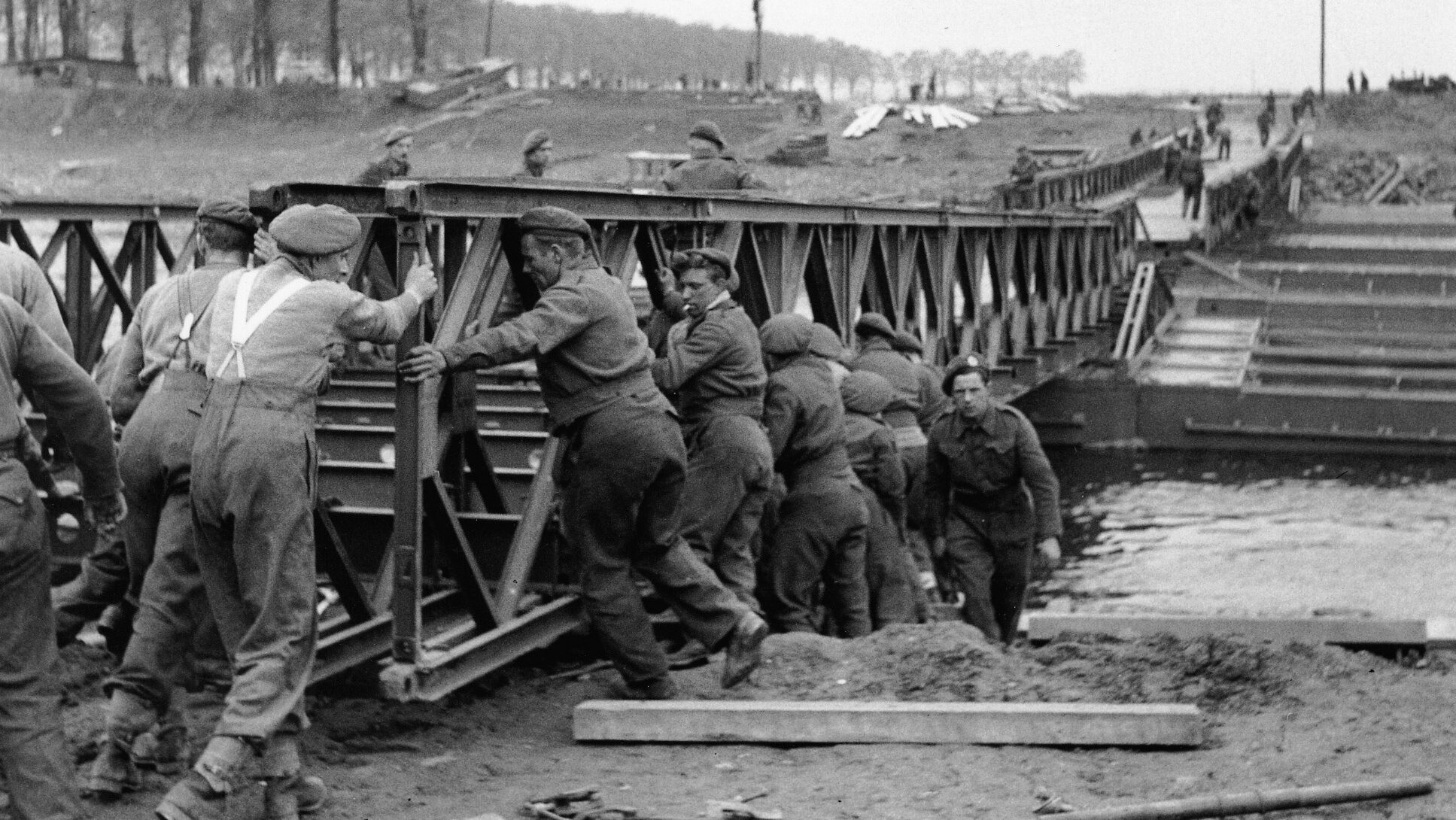
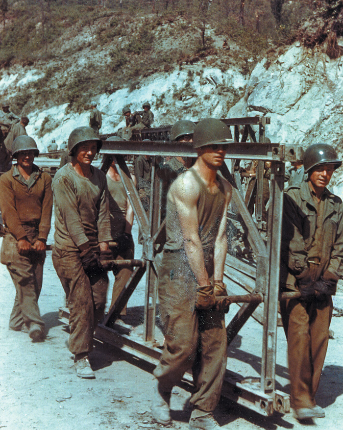
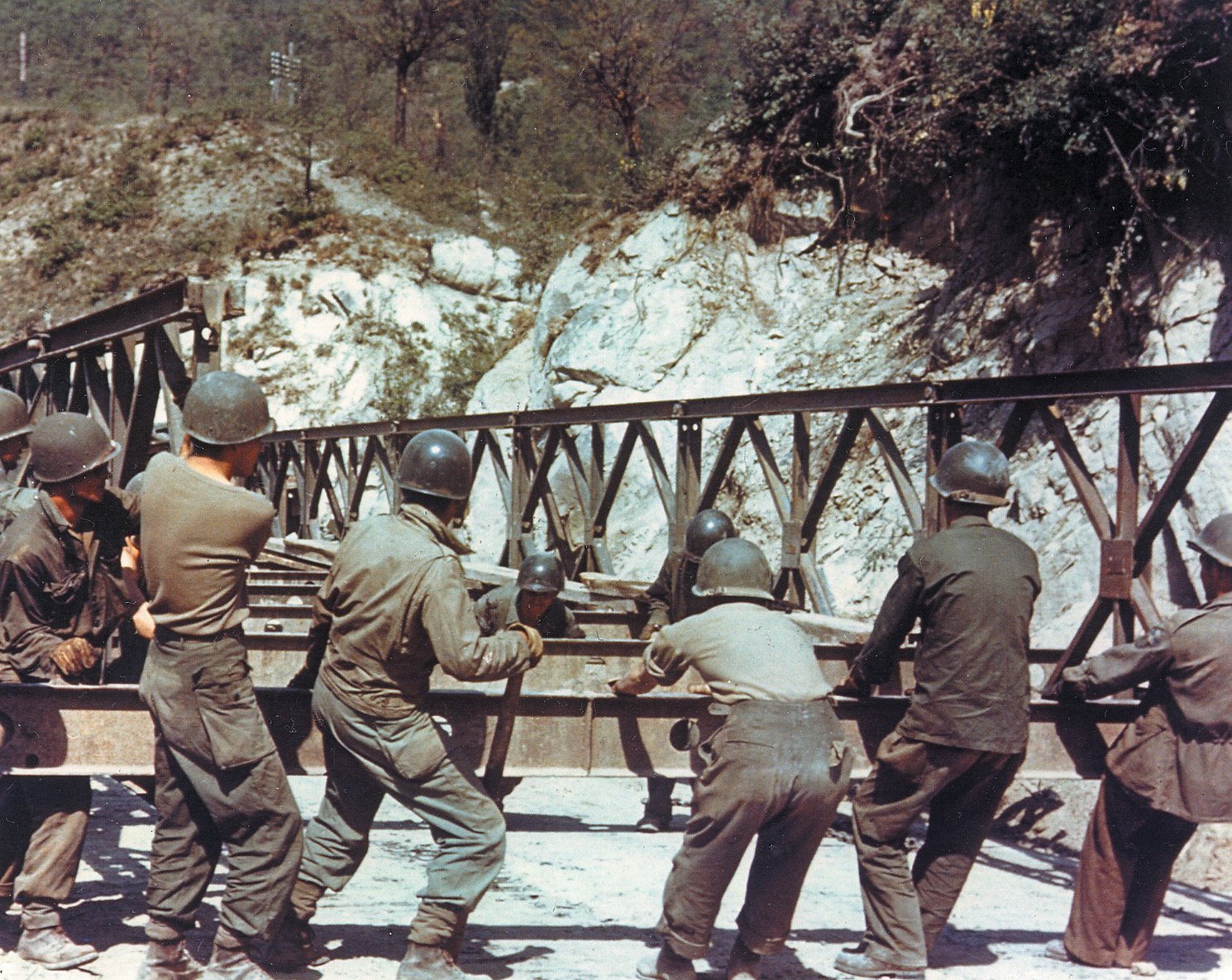
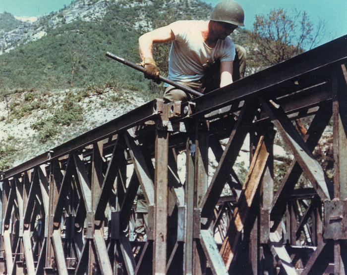
The basic building unit was a welded steel truss. Each measured ten feet long and five feet wide, with three cross beams at each end and at the center, dividing the rectangular shape into two squares. Eight interior beams reinforced the corners of the squares, like geometric diamonds drawn within each. The panels weighed 600 pounds and could be carried by six men. Three pairs of engineers stood at the front end, the middle, and the back. Standing nearly shoulder to shoulder—with the panel standing on its longer side between them—each pair of men used a lifting bar to raise and move the panel.
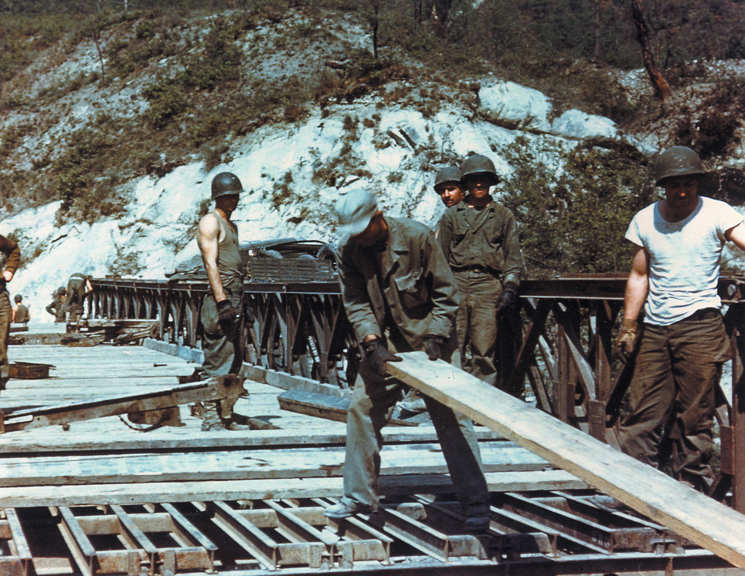
At the four corners of each panel were holes which could be aligned with those of adjacent panels, then secured by pins which were hammered into place, and then locked in with cross bolts. The panels formed the left and right sides of the bridge. Connecting them to form the foundation of the bridge’s road bed were a series of steel beams called transoms, measuring 19 feet in length, laid at five-foot intervals. Laid and secured across the transom parallel to the panels were stringers, smaller beams some 10 feet long. Finally, laid horizontally across the stringers were chesses, wooden panels some 12 feet long, to form the actual road surface that vehicles and men would use to traverse the bridge. These chesses were eventually replaced with steel, since the treads of armored vehicles quickly ripped the wooden planks apart.
Similar In Design to a Firetruck’s Ladder
The idea of building the bridge and extending it across an open space or over water was similar to that of a firetruck’s motor-driven ladder telescoping forward to its target point. The front of the bridge was called, simply, the nose. It was the lightest section of the bridge, consisting of the side panels but without the roadbed and angled upward to compensate for the inevitable dropping downward of the bridge as it expanded across the gap. Behind the nose went the first section, consisting of the two side panels and the road framework. Behind that first section went the second, and the third, and so on. These following sections provided the counterbalance weight necessary to prevent the forward—over-air or over-water—portion of the bridge from toppling the entire structure into the gap. The following sections were built upon rollers and, when ready, could be pushed forward, either by hand or with the assistance of a bulldozer or tractor.
Stacking Horizontally and Vertically
To increase the load the bridge needed to carry, the panels could be stacked both horizontally and vertically. The arrangement was designated by the number of panels stacked horizontally and those placed vertically, to add even greater strength. For instance, a bridge with two single lines of panels forming the sides was simply called a “single-single.” Such a bridge spanning a 100-foot gap could sustain a load of 10 tons. Yet one with panels pinned two deep and two high to sustain a much heavier load of 75 tons was a “double-double,” and so on.
The wartime demand for new equipment eliminated much of the delays typical of peacetime planning. The Bailey’s basic design was ready by late 1940. With the assistance of the manufacturing firm Braithwaite & Company, a pilot bridge was built in a field, two feet above the ground, to conduct the initial load bearing tests.
As with any stress test, the aim was to pile on weight until the bridge finally collapsed. Given the pressure to produce results and the limited equipment available, Bailey decided the simplest test was to drive a World War I model Mark V tank onto the bridge and park it in the middle of the span. Weight bearing jacks which had been elevated beneath the bridge to hold the weight were then removed. The bridge held. The test was repeated by, oddly, placing smaller contemporary tanks onto a platform built on the Mark V. The bridge still held.
Fixed or Floating?
Then the Mark V was filled with scrap iron to add even greater weight. Again, the bridge held. By the time the breaking point was reached—far in excess of the Army’s anticipated needs for moving men and equipment—the E.B.E. engineers had created a table to calculate the width and height requirements for the bridge to bear any load, any distance, up to nearly 200 feet. Production for bridges for the army commenced two months later, with finished packages going to the field three months after that. By this time, the U.S. Army was considering the Bailey as well. Current and planned medium and heavy tanks presented the same troubles for the U.S. combat engineers that they did for the British. Again, the U.S. Army had established models, the H-10 and H-20, but they required much heavy lifting equipment and time to build.
The alternative to a fixed bridge was the floating type, with a metal roadbed built on fixed or inflatable pontoons. However, the existing models presented their own particular problems, especially in balance. Even by 1942, training maneuvers requiring tanks to cross the pontoon bridges had their share of accidents. Seven U.S. soldiers died in four accidents caused by tanks falling from bridges which had failed to support them. A better model of a treadway float bridge was later developed and used with great success later in the war, but the U.S. still wanted a sturdier, easier to manage type of fixed bridge.

Greenlighting for Manufaturing
Late in 1942, the U.S. Army’s 551st Engineer Heavy Pontoon Battalion assembled a Bailey bridge 590 feet long supported by 25-ton pontoons at Rome Ferry, Tennessee. Most of an armored division crossed the bridge, which remained in constant use for a week. This combination of fixed and floating elements was deemed superior to any pre-existing model. Although the Bailey was not a perfect solution—it required more parts than the H-10 or H-20, and its roadbed could not be widened without considerable redesign—it solved many immediate problems and was approved.
Thus green lighted on both sides of the Atlantic, British and American manufacturers received contracts to build the bridge, but with a key difference. American engineering firms were contracted to build the bridge kits as a whole. Although some of the smaller parts, such as the panel pins, were subcontracted to associated firms, each company undertook the responsibility to build every single piece required for the bridge. In contrast, the British government divided the work among some 650 firms all across the United Kingdom. Each operated under rigid guidelines to ensure absolutely that each piece was truly interchangeable with any other. Thus, for example, if pins made by a company in Birmingham were shipped to a Royal Engineer company in India, the engineers could confidently use these pieces with bridge panels that had been built at a factory in Coventry.
Put to Work in North Africa, Sicily, Italy and Northwest Europe
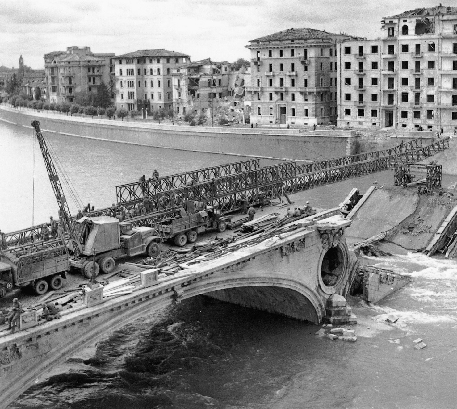
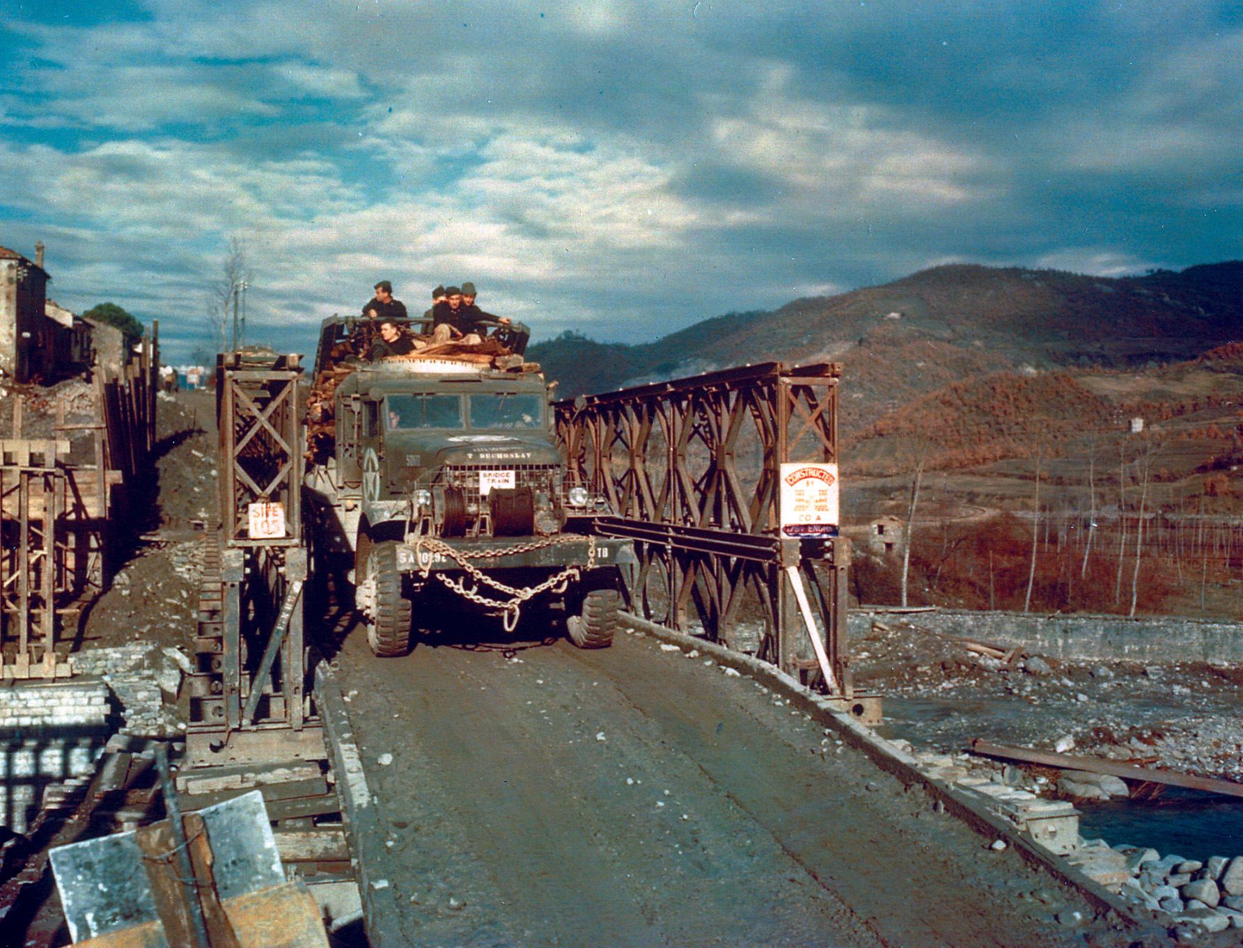
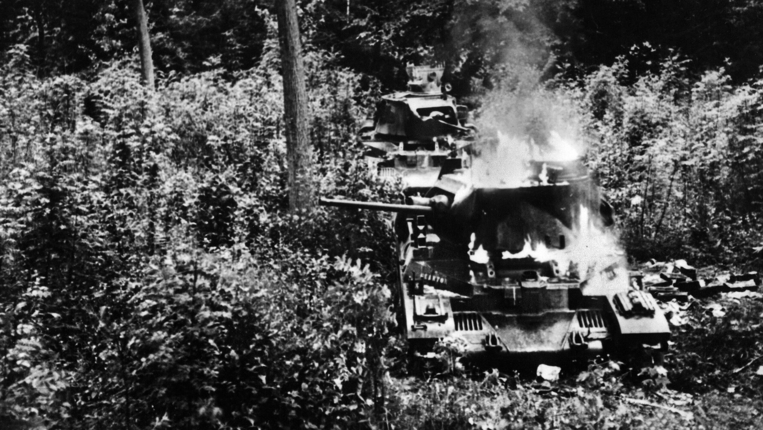
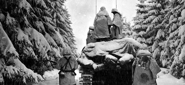
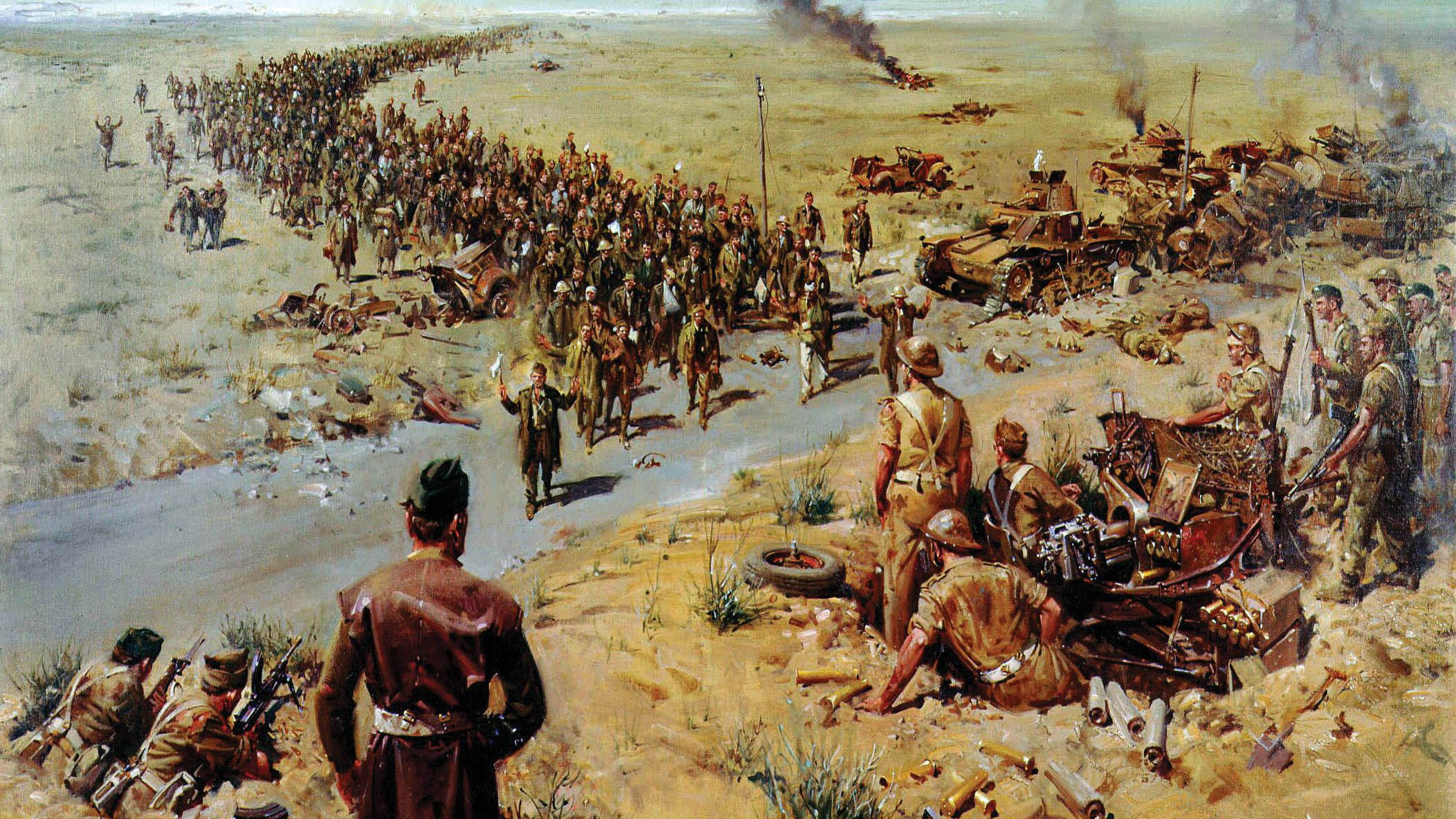
Bailey bridges were put to work by the British and American armies in North Africa, Sicily, Italy, and finally in northwest Europe. As the German forces retreated on each of these fronts, they made liberal use of explosives, mining every road and bridge between them and the Allies. Often, when destroying fixed bridges over rivers, the Germans would blow up one or more of the steel spans but leave the stone or brick piers in place. To the Germans’ dismay and regret, these foundations provided suitable support points for the Baileys. One striking example was on the site of the Sangro River bridge in Italy. The Germans destroyed 19 of the original bridge’s metal spans but left 14 of the piers intact. Upon them the British built an 1,126-foot Bailey.
A serious problem arose in 1944, when the U.S. 31st Engineering Regiment found that several panels were either slightly too large or too small to use properly. The larger panels needed to be ground down to fit with others; the smaller ones had to be cut and re-welded to reach their intended dimensions. This trouble was ultimately traced to a series of fabrication gauges whose accuracy had been ruined through poor handling and bad (if any) maintenance.
Precision Was Vital
Precision was absolutely essential to ensure that every single piece met the required sizes. This discovery came late, after hundreds of American-built Bailey kits had already been sent to Europe. Some 850 of them had to be tracked down and marked as stand-alone types, not to be intermingled with any others. It was an ironic reflection on the British engineers’ success at maintaining consistency of production through the hundreds of factories involved, compared to the relative few American firms tasked with the same work. This did not change the fact that, considering the huge number of men, vehicles, and equipment it helped transport, the Bailey became one of the best pieces of military machinery in history.
Building and using them was not without risk for the basic, serious reason that bridgeheads nearly always came under enemy fire. Europe’s rivers and tributaries made fine defensive borders for the Germans as they retreated eastward during the autumn and winter of 1944-45. Since Allied engineers were building the means for the armies to advance, they were regularly shot at.
Edmund MacNeil of Lynn, Mass., was a warrant officer with the 284th Engineer Combat Battalion, 9th Infantry Division. “When you’re building the blasted thing,” he recalled bitterly, “the Germans are throwing mortar shells on top of you all the time. It wasn’t a smooth operation. There was always a problem. Especially when a plane came over and dropped a bomb on the damn thing, right when we were halfway through building it. Or they’d machine gun us. Or we’d run into mines.”
“All You’d Hear, Beyond the Hammering Were the Sergeants”
Granting the comparative simplicity of assembling the bridge, MacNeil added, “Yes, you can build a Bailey bridge and fly the American flag on each end and have pictures taken and everything. That’s great. But you take the same group of people who are involved in putting a bridge in under combat conditions? Completely different world altogether. The sledgehammers would be going like crazy. You’re slamming pins in all over the place. You didn’t have to tighten up any bolts or anything. You’d just bang ‘em all in there.
“You’d have a sergeant in charge of the assembly,” he continued, “with an officer who’s overseeing everything to make sure everything arrives at the same time and is where it should be. They did a good job, too. I’ve seen officers in there, swinging hammers, trying to inspire the troops to do a little bit more. When a section was ready, and you had enough sections behind for the counterbalance weight, you’d roll the whole thing forward with a D7 or a D12 tractor pushing it all.
“The building would go on, night and day. Once you started, you didn’t stop for anything. You could be two days, three days on a bridge sometimes, and never even know when your next break was. And the faster you wanted the bridge done, the more men you could put on there. We could take eighty men—a whole company—and put them on that project, and then have another company as a ready relief force.
“All you’d hear, beyond the hammering, were the sergeants. ‘Get that sonofabitch!’ ‘Wham that!’ ‘Hit that! Don’t you know how to hit that?’
Always Another Bridge Needed
“Guys would jam their fingers. Break their hands. Break their arms. If you fell down, you’d most likely crack all the teeth in your mouth. And you always wore your helmet. Always. Because if you fell, you were falling on steel. A man would fall overboard. We’d get him and pull him up, and he’d have a bullet hole in him. That happened. German machine guns would wipe out four or five guys standing on the bridge. But it was the only way we could do it, to get across the river.”
Finally, they would cross, usually under cover of Allied artillery and air support, to keep the Germans at bay. Soil and stones required tending, as well as steel. The bridge needed graded approach routes, so vehicles could drive up to it, across, and then down the far side. The bridge’s far side needed to be secured, anchored in the far bank as firmly as the one from which it was built.
“Once we got a bridge done,” MacNeil concluded, “and we were across and moving forward, we wanted nothing to do with that bridge again. Nothing.” That is, until they were assigned to build the next one. The scope of the Allied campaign and the nature of European geography guaranteed that there would always be another bridge needed.
Over 3,000 Baileys Stretching 55 Miles
The German practice of destroying or mining bridges and roads in Sicily and Italy was so thorough that the U.S. Fifth and British Eight armies built over 3,000 Baileys with a combined length of nearly 55 miles, at an average length of 100 feet. In northwest Europe, the U.S. Third Army employed nearly 27,000 feet of Baileys of varying lengths.
During the last year of the war, Allied engineers employed both Baileys and the floating treadway type of bridge, and often a combination of the two, depending on what the circumstances required. The treadway type was easier to transport and build than the Bailey and required fewer parts.
The Bailey, however, was worth the trouble. It was revolutionary in both military and civilian transportation. Nearly every Allied nation employed it during the war and continued to build it in their own country and abroad during the six decades since the war’s end. British Field Marshal Sir Bernard Montgomery and General Dwight D. Eisenhower, supreme Allied commander, both praised the bridge as one of the best pieces of equipment in the Allied arsenal and a vital contribution to their ultimate victory.
The remarkable structure had literally begun with Donald Bailey sketching on the back of an envelope.
My Father, Thomas Sydney William Cleary reported to Sir Donald Bailey and Major Ralph Freeman.
He was the “precision” enginer who argued and won the day.
B 21.1.1907 d.o.d. 15,6,1975
He was the Royal Engineer who was fostered by RE Command. His father died WW1 17.11.18 AMIMechE
Send for his obituary
[email protected]
As a Peace Corps Volunteer in Ghana in 1967-69, I had the pleasure of crossing over multiple Bailey bridges. From WWII to late 60s and who knows when, the iron bridges had long, serviceable, and useful lives.
We lived in Papua New Guinea from 1999-2013 and Bailey Bridges are still in wide use there as existing bridges and to replace damaged or destroyed bridges – along with the Marsden Matting….
My husband was an Army Battalion Commander whose job was building Bailey Brides over German rivers in WW II. He was there during the birth of his first child, a daughter, named Marsha Gail Heald, now Trenbeath, who now resides in Braselton, GA., with her hubby Steve Trenbeath. After WW II he returned to Omaha and took over the Family business. He passed away in 1992.